Main Circuit
The main circuit is the power conversion section that provides adjustable voltage and frequency power to the asynchronous motor. The main circuit of an inverter can be broadly divided into two categories: voltage-source inverters convert DC to AC from a voltage source, with capacitors used for DC circuit filtering; and current-source inverters convert DC to AC from a current source, with inductors used for DC circuit filtering. It consists of three parts: a rectifier that converts the mains frequency power to DC power; a smoothing circuit that absorbs voltage ripples generated in the converter and inverter; and an inverter that converts DC power to AC power.
Rectifier
Diode-based converters are widely used to convert mains frequency power to DC power. Two sets of transistor converters can also be used to construct a reversible converter, which can perform regenerative operation due to its reversible power direction.
Smoothing Circuit
The DC voltage after rectification by the rectifier contains ripple voltage at six times the frequency of the power supply. In addition, the ripple current generated by the inverter also causes fluctuations in the DC voltage. To suppress voltage fluctuations, inductors and capacitors are used to absorb pulsating voltage (current). When the device capacity is small, if the power supply and main circuit components have sufficient capacity, the inductor can be omitted, and a simple smoothing circuit can be used.
Inverter Unlike a rectifier, an inverter converts DC power into AC power at the required frequency. By switching six switching devices on and off at predetermined times, a three-phase AC output can be obtained. The switching time and voltage waveform are shown as an example using a voltage-type PWM inverter.
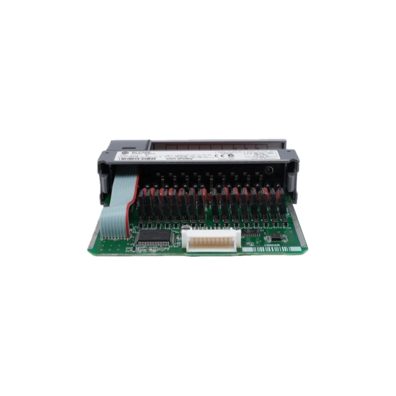
The control circuit provides control signals to the main circuit supplying power to the asynchronous motor (voltage and frequency adjustable). It consists of a frequency and voltage "operation circuit," a main circuit "voltage and current detection circuit," a motor "speed detection circuit," a "drive circuit" that amplifies the control signals from the operation circuit, and "protection circuits" for both the inverter and the motor.
(1) Operation Circuit: Compares external speed, torque, and other commands with the current and voltage signals from the detection circuit to determine the inverter's output voltage and frequency.
(2) Voltage and Current Detection Circuit: Detects voltage and current, isolated from the main circuit potential.
(3) Drive Circuit: Drives the main circuit components. It is isolated from the control circuit to enable and disable the main circuit components.
(4) Speed Detection Circuit: Uses the signal from a speed detector (TG, PLG, etc.) mounted on the asynchronous motor shaft as the speed signal, which is sent to the arithmetic circuit. Based on instructions and calculations, the motor can operate at the commanded speed.
(5) Protection Circuit: Detects the voltage and current of the main circuit. In case of overload or overvoltage abnormalities, it protects the inverter and asynchronous motor from damage.